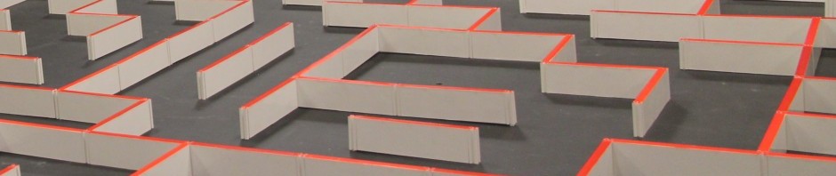
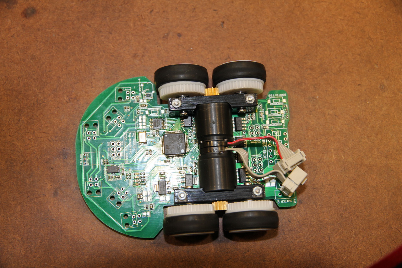
I had most of my part assembled last weekend, turned out gears meshed pretty well to each other, all critical parts are successfully soldered on board without taking any damage.
there are still couple 0603 resistor and 1206 100us tatanlum resistor need to solder, nothing much left, Mouse will be able do a simple maze search this weekend after I can finish rest of the part.
I wrote all code needed in order to make a simple maze search. I even wrote functions for HCMS-2903 LED display with display string, integer, scroll message, etc, even created several customized simple Chinese characters :), I really don’t have anything can do at this moment before I make my mouse fully assembled. The only thing I haven’t done is the code for EEProm since I2C on STM32 is not that easy to use, anyway, I won’t need that this early.
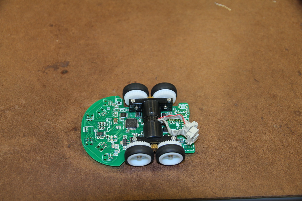
 I didn’t put sensor on since sensor mount will be the last part I will put on PCB.
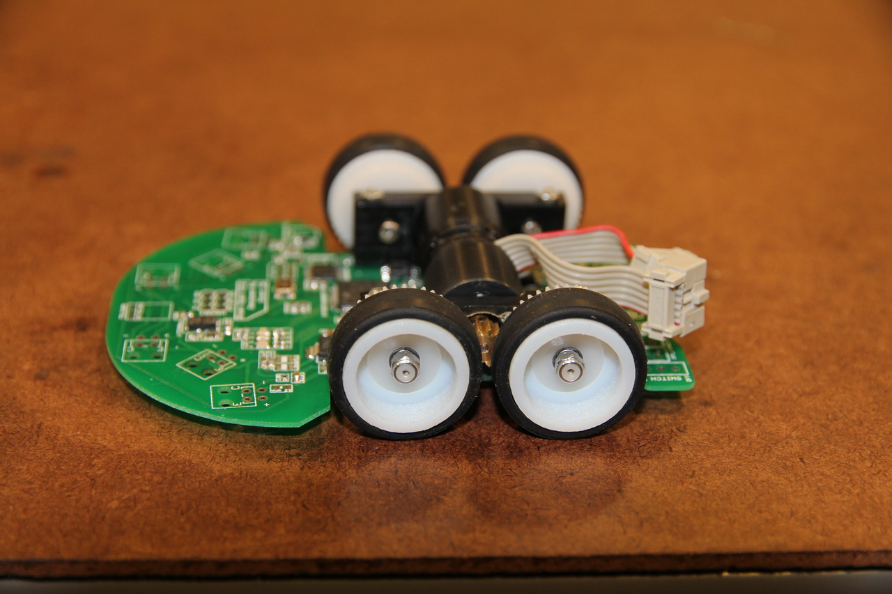
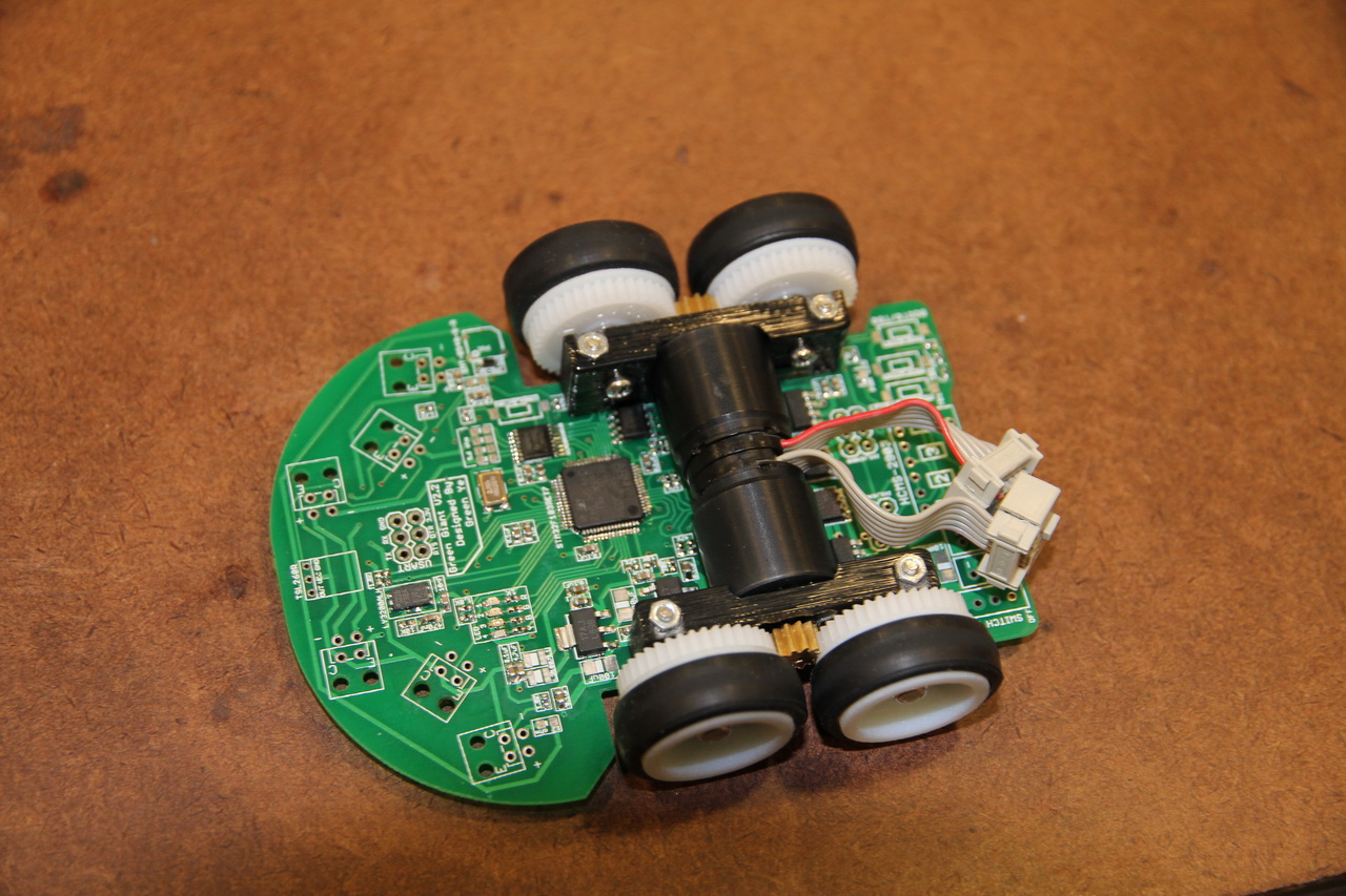
3D printed wheel fitted gear wheel, totally press to fit, didn’t even need to put glue on.
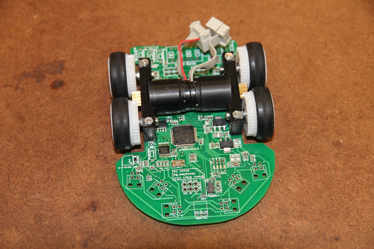 the front is pretty empty since I put lots of components to the back, that was the reason I made my lighter version by mill the front area off.
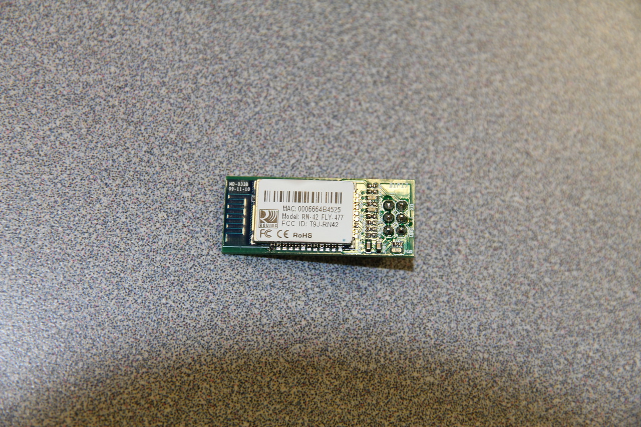
customized bluetooth adapter board.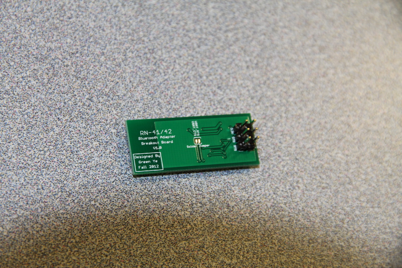
back of bluetooth adapter
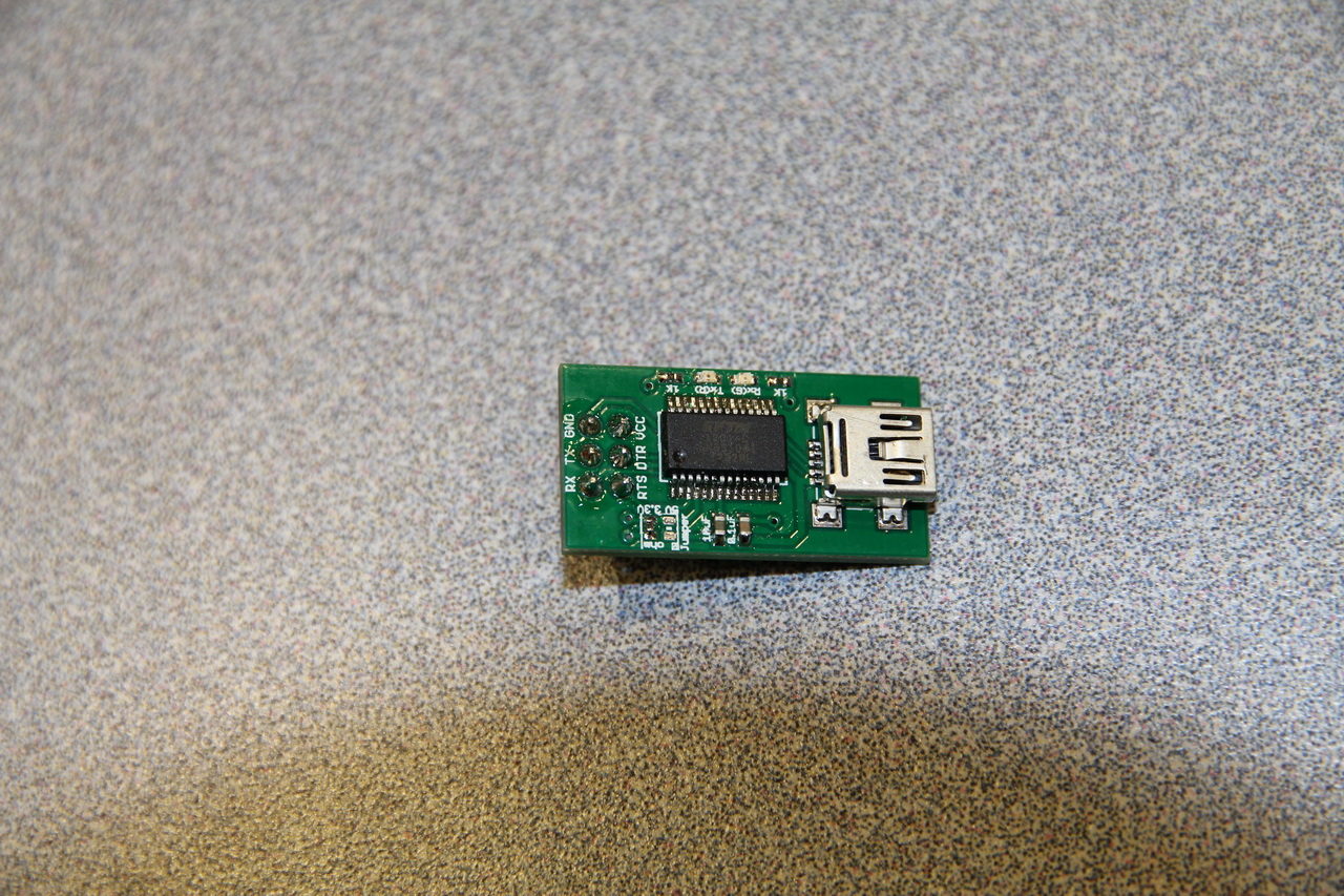
customized FTDI board
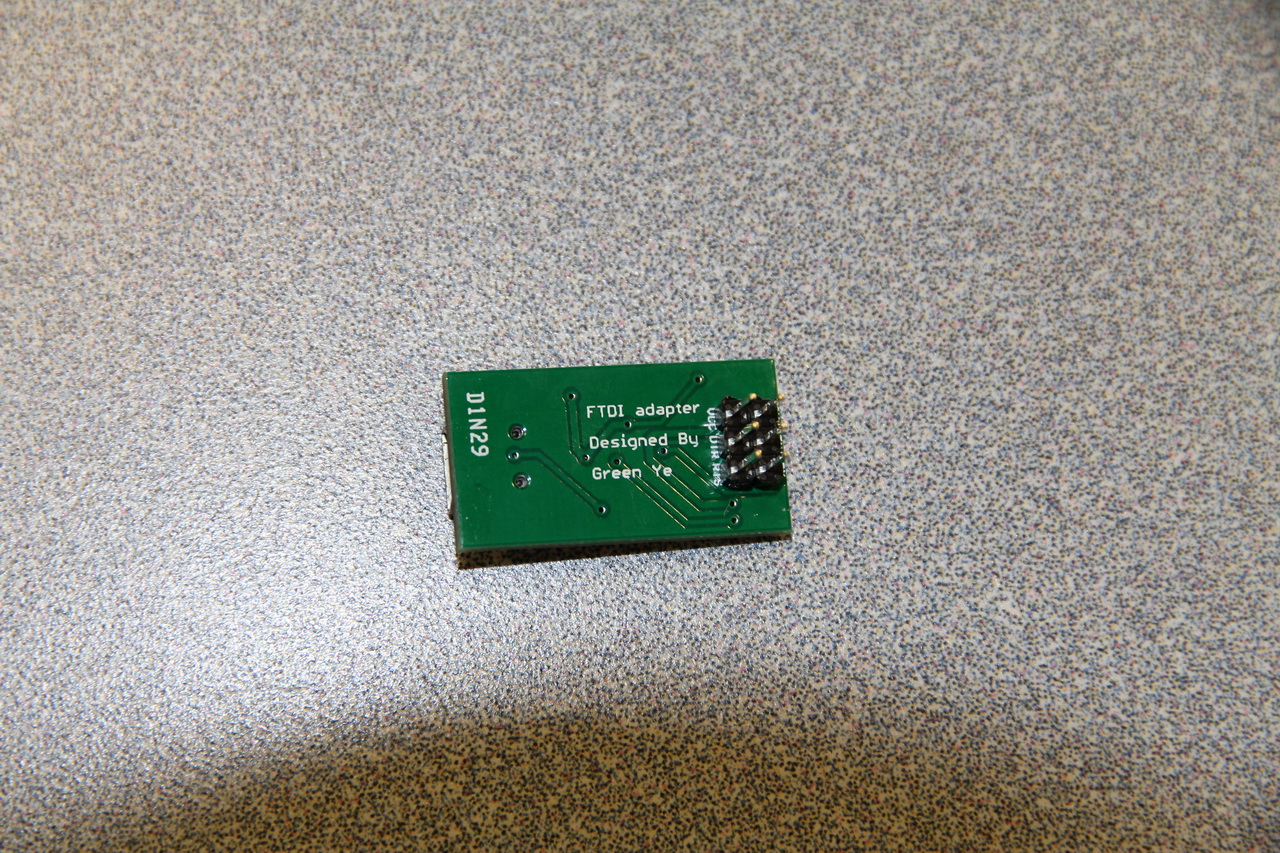 back of FTDI board
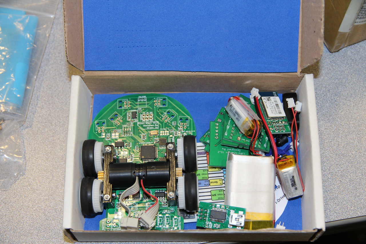 I put everything into the same box that I used last year for holding my old mouse, hope this one won’t get burned…
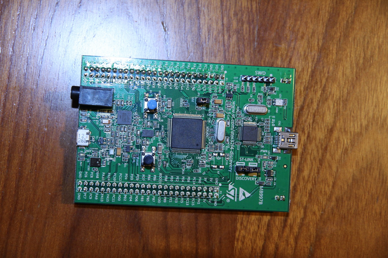 got my STM32F4 Discovery board, start to test on it now, super convenient to download code with ST-LINK with just one click in KEIL.

Where did you buy these LCD display? I was search for this LCD, but I only found very expensive price….
what LCD? I use HCMS-2903 dot matrix led display, it’s available on digikey and mouser.
Hi, I like your design, I wonder if you sell and how much is the cost for the entire mouse, I appreciate you send me the answer to my email thanks. zeaedu@gmail.com.
I am glad you like it, however, I am not going to sell this one. Make a mouse of your own is pretty fun thing to do.
then to start, thanks
Hello,
What are the motor spec you are using?
For my project I could only get a motor with 100RPM @ 1kg/cm torque @ 3volts brushless motor. I am still looking for a better motor. Your inputs will be highly appreciated.
Hi
I am using Falhaulber 1717T 6V motor, it attached with a 512pulse/revolution quadrature encoder.
It has 14000 no load RPM and 5.38mNm torque at 6V.
the spec is here http://www.faulhaber.com/uploadpk/EN_1717_SR_DFF.pdf
Most of people in the world use 6V version and a few of them use 3V version, I also saw someone use 9V version but ideally 6V and 3V versions are good for a 1-2 lipo battery system. By the way, you need to gear it down to gain more torque since this is not brushless motor.
Hi Green, how did you press the pinion onto those motors? I currently have a set of the motors (secondhand) that have pinions on them. However, I would like to remove them and put another set on. It seems to be a very tight fit, and I worry about breaking the motor. Can you provide some advice? Thank you!
Hi Galen,
Basically I used epoxy glue to glue the gear onto the motor shaft. If the motor you bought was falhaulber motor as well, trying not to just simply pull it hard from the shaft, I kinda damage my right motor a little bit during APEC when I was trying to pull it out with plier. Best you can expect is that that gear as press to fit kind and you will be able to pull it out little by little. Harjit also suggested to heat the gear if it is glued, and you need to have something connect to the shaft to transfer heat so it won’t hurt the encoder to the back since the shield for encoder is plastic. gear attached on shaft from manufacture are likely press to fit, and you can try to pull it out. There might be a worst case here that the gear is being soldered on the shaft. In this case, I don’t have good suggestion on it.
Okay, thank you. I shall try it. Congratulations on your success, it is very impressive how your mouse performs so well. Do you utilize post/edge detection? Also, how strict are your motor controllers? Finally, what is your range of ADC values to wall distances? Thank you for your help, it is very kind!
Yes, I use diagonal sensor to detect wall to no wall transition on every cell that the mouse going straight away. I just simply use PD controller on my motor based on the encoder and gyro feedback to make it go straight and make curve turn. But I did spend lots of efforts to tune the perfect Kp and Kd for both transitional and rotational movement. The controller that I am using is developed by Ng Beng Kiat, and I believe a lot of people are using this. My ADC is 12 Bit so the range is 0-4095. My sensor reads pretty far, and the reading is 0 when the object is infinitely far from sensor, and when the mouse stay at center of cell, the front sensor reading are like 3600 out of 4095 ish. Somehow I feel I made the reading too strong,and I might need to reduce the pulsing time to prevent saturation when ambient light is too strong(such as Sun Light or Flash). Hope all these above will help.
Thank you! That was very helpful. I also use a controller similar to Ng Beng Kiat. However, I cannot figure out how to add in the wall/nowall transition in. Could you help in that area? Perhaps a post would be very helpful. 🙂
that’s actually what I planed to do on calibration strategy part 2. All America Micromouse Compensation is this coming Sunday so I might have time to do it afterwards.
here is what I do for wall-to-no-wall transition:
I use 2 booleans for left and right wall cases.
I only use left wall as example here, same process for right wall. it’s OK that detect the transition for wall to no wall on both side at same time. The later finished one will just overwrite the result of older one.
if left sensor reading greater than threshold A, booleans is true(we find a wall or post)
then we keep checking until the sensor reading smaller than threshold B and also boolean was true until the last time I checked the wall or post, then we exit the case, and this is where wall to no wall is detected. then we just overwrite the remaining encoder distance that the mouse need to go for this cell.
threshold A should always slightly larger than threshold be to make the logic more strict to prevent the detection being triggered and exited by accident. But it works if you make threshold A = threshold B
It will make more sense if I explain it with a graph. and the threshold for post to no post is different with wall to no wall, so you need to have separate cases to with them in order to make the longitude distance calibration accurate.
Hello sir , we r truly inspired with your project and trying to implent . Can u please tell us that which controller have you used for this project . ( Name of that IC). And also the Sensor Name. Thank you. Looking for your kind cooperation.
I had these included on project futura page on this site.