
Since pulse controlled are getting pretty popular these days, emitter need to be turned on with a current higher than forward current at a relatively short time period. Usually, the turn on time is under 100us in order to make receiver receive sufficient reflection light. Some people like Ng Beng Kiat use an additional timer to trigger DMA associated with NVIC to scan ADC between different channels, the whole process is relatively complicate than only using ADC to receiver sensor signal without using Direct Memory Access(DMA).
I used a different way in order to simplify the process by utilizing the tracked system time in micro second, here is the sample code
/********* adc1 setup **********/
//call this function in int main() to initialized ADC
void adcConfig(void)
{
ADC_InitTypeDef ADC_InitStructure;
RCC_ADCCLKConfig(RCC_PCLK2_Div6);//ADC works at 72/6=12MHz
//* ADC1 Configuration *
ADC_DeInit(ADC1);
ADC_InitStructure.ADC_Mode = ADC_Mode_Independent;
ADC_InitStructure.ADC_ScanConvMode = DISABLE;
ADC_InitStructure.ADC_ContinuousConvMode = DISABLE;
ADC_InitStructure.ADC_ExternalTrigConv = ADC_ExternalTrigConv_None;
ADC_InitStructure.ADC_DataAlign = ADC_DataAlign_Right;
ADC_InitStructure.ADC_NbrOfChannel = 1;
ADC_Init(ADC1, &ADC_InitStructure);
ADC_Cmd(ADC1, ENABLE);
ADC_ResetCalibration(ADC1);
while (ADC_GetResetCalibrationStatus(ADC1))
ADC_StartCalibration(ADC1);
while(ADC_GetCalibrationStatus(ADC1));
}
whenever I need to read ADC data, I call this function as follow to get ADC value in 12 bits resolution by taking 28.5cycles equivalent time.
u16 readADC(ADC_TypeDef* ADCx, u8 channel)
{
ADC_RegularChannelConfig(ADCx, channel, 1, ADC_SampleTime_28Cycles5);
ADC_SoftwareStartConvCmd(ADCx, ENABLE);
while(ADC_GetFlagStatus(ADCx, ADC_FLAG_EOC) == RESET);
return ADC_GetConversionValue(ADCx);
}
now is the process about how I use pulse control to read IR sensors. Here is the sensor configuration that I used for one of my mice with 4 sensors. left and right sensors emitters are serial to each other; left front and right front emitters are controlled individually.
Since I serial a very low value resistor with emitter in order to make instant current higher than 100mah forward current, I have to turn on emitter for a pretty short time to prevent it burns out before receiver can start to ADC converting. However the advantage for pulse control sensors are also obvious: you will be able to send a very high signal from emitter to significant against ambient light, and your reading range will also be increased.
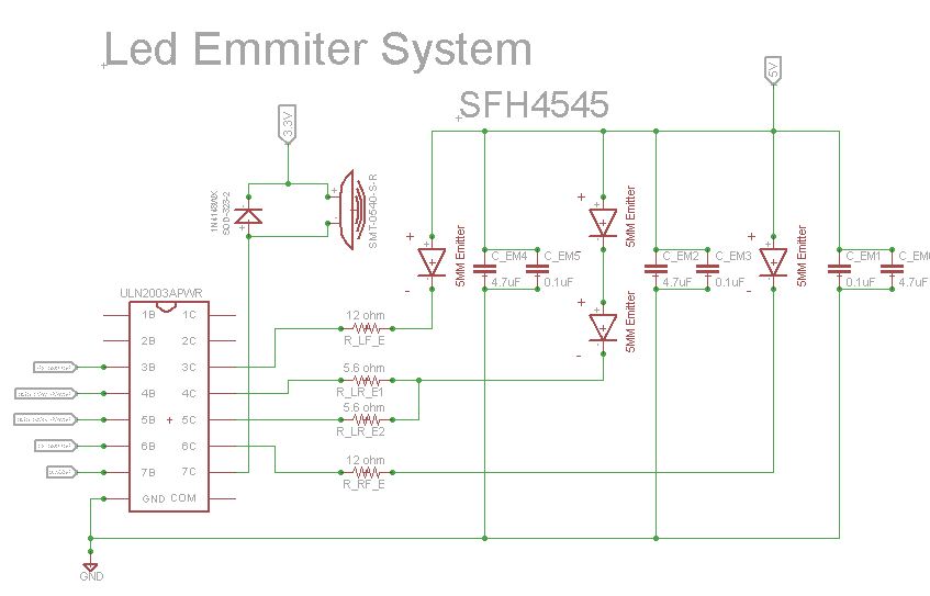 emitter system
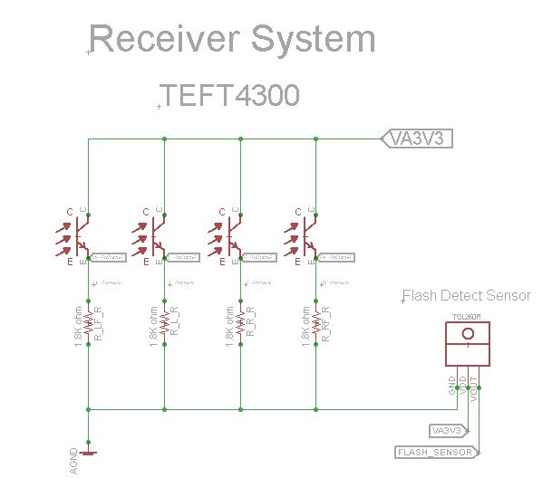
receiver system
Here is what I proffered for my pulse control process:
For the emitter I use, SFH4545, I usually prefer to turn on emitter for 60-80us, then do ADC converting for the corresponding receiver, then turn off that emitter, wait for 80us until the infrared light from this emitter is totally disappeared to make sure rest of the receivers won’t get any light from this emitter. After that, I just repeat the process again for next sensor.
Here is my code
Void readSensor(void)
{
int curt = micros();//record the current time
LF_EMITTER_ON;//this is not sudo code, this is macro I defined somewhere else
While((micros()-curt)<60);//use up time until 60us from where we record curt
LFSensor =readADC(ADC1, 7)//PA7 ADC1_IN7
LF_EMITTER_OFF;//turn off emitter right after receiver done ADC converting
//do linear regression here for left front sensor if you plan to linearize your sensor
While((micros()-curt)<140);//140-60=80us,wait 80us until reflection is gone
RF_EMITTER_ON;
While((micros()-curt)<200);//200-140=60us, turn on emitter for 60us
RFSensor=readADC(ADC1, 3);//PA3 ADC1_IN3
RF_EMITTER_OFF;
//do linear regression here for right front sensor if you plan to linearize your sensor
While((micros()-curt)<280);//280-200=80us
SIDE_EMITTER_ON;//turn on side emitters for side sensors
While((micros()-curt)<340);//340-280=60us
leftSensor = readADC(ADC1, 5); //PA5 ADC1_IN5
rightSensor = readADC(ADC1, 4); //PA4 ADC1_IN4
SIDE_EMITTER_OFF;
//do linear regression here for side sensors if you plan to linearize your sensors
}
Thus you have all your sensors easily read with pulse control. The process is much easier than using DMA triggered by timer, even though DMA does make it slightly faster for converting. In this process, my case spent about 340us with 4 sensors, and it will take 480us on my 6 sensors micromouse, after all, there is still 520-640us left for you to something else for you interrupt service routing if you sample every 1 ms. On other hand, your power consumption is fairly low since you don’t turn on your emitter all the time, you can also turn off all your emitter before this process to let all receiver to pick up environmental light then subtract from it later when emitters are on in order to reduce noise.

Hi,
In the emitter circuit i notice that for the diagonal sensor there are two power modes,one with only one of the two parrallel 5.6 Ohm resistors on and one with both output active. Can i ask why?
that is for current adjust purpose. if only one transistor is on, total resistance when through 2 diagonal emitter is only 5.6 ohm, when both transistor on, since two 5.6 ohm resistors are parallel to each other, the overall resistance become 5.6/2 = 2.8 ohm, thus the current go through 2 serial emitters get higher. This setting is not necessary if the value is for resistor is tested ahead of time. I had this idea from Ng Beng Kiat, just in case you you need high current for diagonal sensors.
Thank you for the fast answer.
I have another question that is a bit off topic with the previous..What is the distance from the ground of your mouse? What you would reccomend?
I had 3mm clearance for my mouse and I think it’s a little bit too high for me since I saw other entries from APEC had like 1-1.5mm clearance for there 4 wheel mice. I plan to lower my clearance in the future but for your case, since I don’t know your design and the maze you are possibly going to use, technically, as low as possible to lower the CG but at same time you need to consider if it will be too low to stuck at the gap between maze board connections.
Do you have any problems with receiver noise? Are you using any filter?
I didn’t use any filter for receiver output.
You need to do power conditioning for analog device(aVCC and aGND)
I want to ask what flash detect sensor use for?
teft4300