
For those who know successfully downloaded code to STM32 through built in ISP must remember that you have to hold boot0 button(assume boot1 is already pulled down) then press reset button then release reset button in order to switch to ISP mode for stm32 to download code into flash. To be honest, I quit enjoy the moment to hold and release the boot0 button when downloading code(I am not a big fan of STMlin btw :D), but this is not quite true for all cases.
Those who don’t have sufficient space on their micromouse PCB always tend to choose smaller buttons to save space. However, these buttons are definitely not as easy to press as those normal size buttons, it becomes pretty painful when you need to press more than one button at same time such as operating boot0 and reset buttons at same time to download code.
Of course, there some develop board who use STM32 as their MCU have some auto download circuit, but since you usually make your own minimum system on mouse PCB, you won’t be able to utilize these features on other people’s products for sure. Auto download circuit can be achieved by having a additional micro-controller, but this is not what we are going to do today.
In fact, I found a software has such as function to utilize RTS and DTR on FTDI programmer IC to control the behavior of BOOT0 and RESET with some simply modification on your STM32 circuit.
Firstly, here is the screenshot of this magical software, named “FlyMcu”
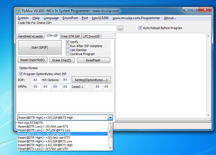
it supports both LPC and STM32 ISP mode
I use RS232 USB to serial programmer IC to make a FTDI board to download code from PC to STM32, I reserve a 6 pins port on my micromouse. They are TX TX GND 3.3V DTR and RTS. I think you guys know TX and RX already, since TX RX and GND is the minimum requirement for download code through serial port. DTR are RTS are some other functional pins on traditional serial port on your PC(a 15 pin port. even though most of the new PC no long have it). What we are doing here is let the software flymcu to control these 2 pins through USB to serial IC to automatically send high or low with a certain order you define.
I decided to use DTR to control reset and use RTS to control boot0.
Let’s look at the modified circuit
BOOT0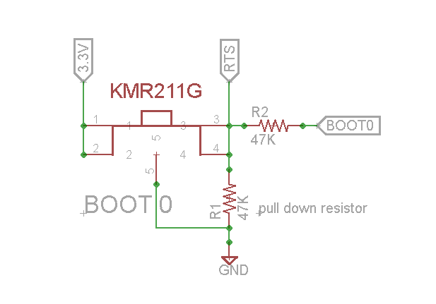 Circuit
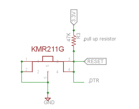
Reset circuit
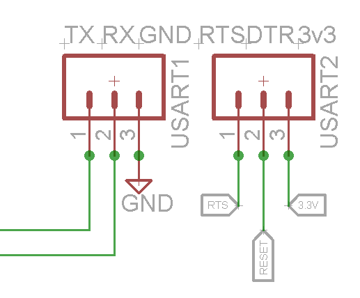
pin order on my 6 pin port on micromouse
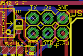
schematic for 6 pin port on micromouse
Basically this circuit set will make it available to do both manual and automatic code download. The way that flymcu does with my circuit setting is to send low signal to DTR(connected to reset) to make the voltage on RESET to be low then send a high through RTS(connected to BOOT0 though a current limit 47K resistor) to set the voltage at BOOT0 as high, then stop sending low signal to DTR, since I have a pull up resistor on reset, the voltage on reset back to high(which is no longer low). thus, your STM32 is in ISP mode now, flyMCU will then automatically download the hex file you selected to your STM32 right after finishing control of DTR and RTS.
In this case, you are no longer need boot0 and reset button on you micromouse now. I still keep them both since I sometime do need to press them for fun : ) . This method can also make you download code automatic and wirelessly if you have a bluetooth adapter who has DTR and RTS.
If you use some of the NXP LPC series cortex arm M3/M4 processer, you can also use this software do make a auto download system since LPCxxxx also has such a similar mechanism to trigger ISP mode like STM32.

Nice solution. It make sense, if you use bluetooth module to upload program, like cheap HC-05/HC-06, but if you want to download code to stm32 via wire, it’s better solution – DFU bootloader, so you can download code directly via USB. Check this out: http://leaflabs.com/docs/bootloader.html – Simple method to download your hex file without touching any buttons, and using any ftdi or similar dongle. Additionaly, mini/micro USB connector is smaller then 3×2 pinhead 😉
Hi,
I had experience for using maple mini before, I was surprised that leaflabs made it work without FTDI chip. STM32 built in native USB, all we need is just the proper bootloader to drive it. I probably won’t go for use solution since I have sufficient spacer and USB port is metal which adds weight more than plastic. I made my FTDI board by myself, and it will be fun to keep using serial output other than USB since I am not quite familiar with that bootloader interface, and I may need to do some circuit modification.
Hi,
I’ve tried something quite similar with a FT231X chip, and I can toggle rts and DTR to get to the bootloader fine. However, when just powering up (on my robot) the FTDI chip toggles those pins somewhat unpredictably (for serial handshaking) and this sometimes inadvertently puts my microcontroller in boot mode when I just want it to run my code. Have you ever had this problem, and do you have any ideas to fix it?
try some external strong pull-up or pull down for RTS and DTR. I am so addicting with programmer that one click in keil to download code 🙂 and use FTDI as alternative method to download code.
I have some qestions about circuit connection. On figure “Reset circuit” RESET is connected to NRST on MCU or to BOOT1? How is BOOT1 conneted?
boot 1 is low on my setting.
Boot 1 is pulled down and RESET from figure “Reset circuit” is connected to STM32 pin NRST, right?
yep, Reset is NRST